"The anode current is related in a certain way to the control voltage or effective potential.
In the space charge range the anode current is approximately proportional to the 3/2 power of the effective potential.
In triodes the effective potential is:
Vs=p(Vg+Va/μ)
where μ represents the amplification factor of the valve and p is factor related to the dimensions of the valve and is usually only a little less than unity.
If Va/μ is greater that the absolute value of Vg then, notwithstanding the negative control-grid bias, the effective potential is positive and consequently there is an anode current, which is limited by the space charge, and if the control grid is sufficiently negative then there will be no electron current (grid current) flowing to the grid.
The effective potential is the mean potential in the plane of the control grid. This potential, however, is not everywhere the same and equal to the voltage Vg. In consequence of the potential of the positive anode behind the grid (assuming the anode has a considerably higher potential than that of the grid), the potential between the grid wires is higher than that of the grid wires themselves...
...The field of the anode, so to speak, penetrates between the grid wires." [Deketh]
The potential of Vg is also greatly influenced by the emission of the electrons from the cathode.
Contrary perhaps to intuition the free grid potential is many hundred millivolts negative with respect to cathode when the cathode emits electrons.
If we restrict operation to not too high anode potentials in order to avoid creation of positive ions, secondary emission effects etc...
...then why can't we let the electron tube bias itself without grid current by letting the grid free and adjusting the grid space potential by heater current (cathode temperature) and anode potential (anode potential penetration to grid).
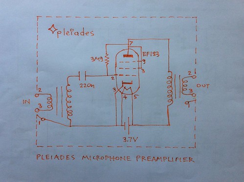
An example is the 1H4 on the Pleiades V6 amplifier operating as a mic booster amplifier, open grid and at 9V to the plate. Perhaps increasing say to 18V anode potential may produce even better results. The anode current at 9V and free grid is approx 10μA. The electron tube amplifier mic sound is big and nice. See relevant post.
One pitfall might be that if the grid suddenly becomes too negative by a signal peak, the electron tube might be blocked, no anode current, no gain and remain at this condition until electrons are removed from the grid.
So perhaps we might need a say 60MΩ resitor from grid to the same potential so that no grid current flows. In fact we do not bias but just help the grid retain its free bias, just in case.
The 60MΩ would produce a release time constant to a possible gradual gain reduction effect of the electron tube by a signal being rectified and a negative bias increasing on the grid while a large signal appears at the input. This is how compressors operate with a side chain diode rectifier. See for example Altec comporsor schematics or RCA BA6A. (Automatic gain control or agc).
This effect seems to be also used in the Neumann U47 VF14 amplifier to reduce the gain of the electron tube thereby increasing the allowed acoustic SPLs to the U47 capsule without amplifier clipping distortion.
In the mean time superb low noise results can be had with an electron tube operating with just 4V at the anode and pull up bias from its negative assumed grid potemtial value. Grid current seems to not matter much on very low level amplifiers. The input impedance is reduced but this helps damp the mic input transformer secondary reasonance. Non linear effects are reduced the smaller the input signal level is. See 1st few terms of Taylor series. (The earth is flat for small excursions). In fact gradual rectifier grid current non linearity may be desired, as a possible gradual agc mechanism? Low anode current or anode potemtial seems not to matter anyway as the microphone signal from a speech level singer is sending a so tiny current or voltage anyway. And we are concerned with the front end, just next to the microphone input transformer. The main interest is great sound and lowest possible noise.
More experiments are needed.
References:
Fundamentals of radio-valve technique - Deketh - Philips Technical Library
Operating features of the Audion - E. H. Armstrong
Pleiades V6 schematic, the Pleiadss bias - euroelectron
Open grid tubes in low level amplifiers - Robert J. Meyer - electronics - Oct 1944
No comments:
Post a Comment