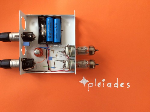
2 stage EF183 electron tube microphone battery field pre preamplifier with proximity compensating input transformer
It took 40 years and a few days.
Balanced input
Microphone proximity compensated input
Unbalanced low Z output or balanced with an output transformer
Uses 2 3.7V Li Ion batteries
Circuit description:
Energy feed first:
The 2 Li Ion batteries and the fuse are in series and the 7.4V are connected to the series heaters. Each EF183 tube feeds from 3.7V instead of 6.3V. This keeps electron emission congestion low so that the tiniest signal from the microphone can be amplified with least noise.
Advantages, portability, no transformers, no diodes, no chokes, no electrolytic capacitors, and above all no countless sources of hum when we want to extract the subtlest nuances of voice.
The negative battery supply is connected to the XLR shield connector and everything negative is star connected there including of course pin 1 (see excellent Jensen transformer papers).
When microphone is connected electrons move back and forth in a balanced way in twisted cables 2 and 3, feeding through the XLR the primary (orange winding) of the microphone input transformer. Common mode signals ie not moving back and forth but in the same direction such as RF and line hum travel along the orange wires and collide with themselves so there are extinguished.
The input transformer is completely symmetric electrical and physically allowing a fully balanced operation with no shield needed. The toroidal core is a Magnetec nanoperm noncrystalline core of extremely high magnetic permeability.
As each electron moves back and forth at the microphone music signal it repels the next electron on the orange twisted cable and so forth so all electrons get to dance!.
Inside the orange transformer coil currents move clockwise anticlockwise dancing to the music.
The core is Magnetec 060, Primary winding is 35 turns and secondary 350 turns.
Jealous electrons see all this spinning in the primary winding and they cant help but spin too inside the noncrystalline tape wound core. Jealous electrons at the secondary winding dance too spinning in a waltz sort of way but since there are 350 turns the corresponding voltage is 10 times.
One side of the secondary is connected to star ground the other to the coupling capacitor to eliminate direct currents to and from tube grid on the other side. It is the dance back and forth component that matters.
When we connect the batteries we have a closed circuit of electrons moving fast through the heaters. Fast electrons collide with atoms and heater atoms move back and forth at greater speeds ie the temperature is greater. Collisions with surrounding cathode inside the evacuated EF183 tube make electrons move faster. Some of them as temperature ie speed is increasing can escape into empty space nearby inside glass.Because of them surrounding space near grid becomes negative repelling further electrons or cathode is positive wrt grid due to lack of them. This is one reason why we do not heat up with 6.3V as there is no point in having billions of electrons move in all sorts of directions when the tiny music signal arriving at the grid has relatively few romantically dancing electrons.
A 4.7Megohm resistor is connected to grid and its other side to positive anode. Its purpose is neutralising the negative potential that as explained exists at the grid so that we can have anode current influenced by the dancing electrons at the grid ie amplification.
To be continued.
No comments:
Post a Comment