Tuesday, July 31, 2018

Τα λάθια ειναι για να μαθαίνουμε


Τα λάθη ειναι για να μαθαίνουμε.


Ακομα και στη μουσική.


Αγγίζουμε το λάθος πλήκτρο, αμέσως ακουγεται λάθος.


Ξανα δοκιμάζουμε μέχρι να ακουστεί σωστά.


Mistakes teach us


Even in music.


We hit the wrong key, it immediately sounds wrong.


We try again till we hit the correct key.


Everything in music is referenced to the white keys


For example C# G# is an interval of 5th, we think of the white notes C, G. We count the white notes or keys. C to G is 5.


Other example. Moonlight Sonata - Beethoven begins with bass C and 1,3,5 on the right hand. Ie C,E,G. Actually they are played in a different order, G, C, E. The key is C sharp minor most of the notes or keys are black. But still even the names are of the white keys. We say C and sharp because it is sharp. C#. And we can think of 1.3,5 as G,C,E but it is G#,C#,E.


And we always write the white notes on the score. But we know from the beginning by special notation at the leftmost part which ones are sharp or flat.


Bonjour à France


Russia top yesterday on euroelectron page views


Then France, China, Germany.

Monday, July 30, 2018

A quick way to sleep in bed


Thinking on building an electron tube headamp.


The best natural marmalade on the planet?


It may be a fig just starting opening itself while on the "wild" tree.


Still dawn cold.


This sweetness is very difficult to match.


Something no money can buy.


It just may happen on your way.


Reach up high enough to find it, or the wild tree leaning towards you.


Hello to France


Hello to Australia


The VF14 on Neumann U47 microphone is heated by 35V instead of 60V, why?


https://www.radiomuseum.org/tubes/tube_vf14.html

Hello to Germany


Why tube bias?


Attention to any voltage. All safety precautions should be strictly followed.


We should not be biased.


Perhaps it might be the same for electron tubes.


Why should they be biased?


What does bias mean? Does it mean a voltage?


By definition the grid potential is the grid potential with respect to cathode [Gray]. So to avoid confusion it is not the potential difference between grid and ground or 0V. It is the potential difference between grid and cathode. This is what matters in electron tube operation. This is why we usually isolate the grid from DC by a coupling capacitor. This is why grid to cathode current flows when we return a resistance to grid. There was already a voltage at grid with respect to cathode. It is generated by the missing electrons from the cathode moving towards the grid. Missing boiling electrons from the cathode leave positive protons behind. So cathode is positive wrt grid or grid is negative. When we close the circuit by a grid return resistive path, negative electrons take this path to return to their beloved positive protons, A current flows.


When the cathode is heated up electrons are emmited and the grid becomes negative. This is its natural electric potential under such conditions. Why not leting it be at that potential?


So the question is:


Do we pull down the grid by what is called negative bias?


Do we pull up the grid potential (still negative but less negative or closer to 0V) by what is called in euroelectron Pleiades bias?


Or do we leave it as is, let it be at its space potential?


1st option allows operation of an electron tube at high to very high plate or anode potentials. More than a hundred volts even for small electron tubes.


2nd option allows operation at very low plate potentials, less than 6V. See Pleiades V series front end amplifiers.


3rd option, free grid, or floating grid or open as it is called grid or grid at space potential allows operation at typically between 10? and 70? volts. Is this what Georg Neumann had in mind when he supplied the VF14 anode of the U47 microphone amolifier by approx 40V. Is the cathode resistor designed to neither pull up, or pull down the grid letting it keep its space potential? Would anode current stay the same if the 60MΩ return resistor was disconnected? Why did Georg Neumann suply the heaters of the VF14 with just 35V instead of 60V? Did he want to reduce the negative space potential at the grid [Atkins] by the boiling electrons? Did he just disconnect heaters and heard an increase in signal to noise ratio?


See also,that the grid space potential can increase when anode voltage is applied:


http://euroelectron.blogspot.com/2018/08/the-grid-space-potential-increases-when.html


References:


Applied Electronics - T. S. Gray - MIT


Low plate potential tubes - C. E. Atkins - Radio & Television News - Jan 1957


Patent US2850674 - Carl E. Atkins


The Pleiades bias - euroelectron


Open-grid tubes in low-level amplifiers - Robert J. Meyer - Electronics Oct 1944


See also some preliminary mic head amp tests:


http://euroelectron.blogspot.com/2018/07/1h4-with-grid-at-space-potential-mic.html


40 pageviews from Russia yesterday


Russia was highest yesterday on pageviews.


Other countries about 10 to 3 pageviews.


China 3 pageviews.


Sunday, July 29, 2018

What could be simpler than a 13CW4 mic booster preamp with a 9V battery, space potential


Batteries, other sources of voltage should always be connected in series with a suitable fuse for safety.


Perhaps simpler is the CV2269 with just one AAA battery, ie Pleiades V1. Or using the Pleiades V6 schematic for a mic booster amplifier. Or the 2DV4 Nuvistor electron tube with an AA battery and Pleiades or pull up bias, not tried yet. A difference between Pleiades V1 and V6 is that the V6 has the output transformer directly connected to the anode, ie no plate or anode resistor. The 7586 Nuvistor has been tried with the Pleiadss V6 schematic at 3.9V at heaters and 1.3V at plate with Pleiadss bias giving excellent sound quality and low noise.


Pleiades V6 schematic


The 13CW4 should be great too as the 9V battery supply may give the opportunity of operating the electron tube at space potential or free grid, open grid, floating grid.


So by adapting the above Pleiades V6 schematic for 13CW4 use...


A 9 volt battery is used in series with a fuse for safety. Heater consumption is low for an indirect heater electron tube.


No pull up or Pleiades bias resistor may be needed.


9V suppies both heaters and plate circuit.


There are at least a few auto compensating mechanisms in this simple circuit.


1 The grid is free to assume the potential by nature. When the battery voltage drops the grid becomes less negative as the cathode emmited electrons are not that energetic near the grid. Anode current should not change much.


2 By not pull up biasing, the anode current should be small but not too small. Therefore the primary of the output transformer which is carying DC is less easily magnetically saturated. But there should be some bass drop because of a relative high internal plate resistance. So somewhat proximity effect, Flecher Munson curves, voice effort curves etc are compensated.


3 at low plate potentials the effective geometry of the electron tube changes [Atkins], μ or amplification factor decreases and there is less chance of overloading the preamplifier following the booster mic headamp.


Underheating and low plate potemtial, open grid should produce low or perhaps very low noise.


A variable inductance with respect to frequency input transformer can be used such as a Freed (see previous posts) for aproaching flat frequency response from producer's brain to listener's brain.


If 9V is not enough for operation at grid space potential then 2 or 3 batteries could be used in series and one of them one supplying the heater. The batteries can be rotated as anode consumes only microamperes.


But even with just one 9V battery a simple world class quality 13CW4, preamplifier amplifier unbalanced or balanced with transformers should be possible.


See also that the grid space potential can increase when plate voltage is applied:


http://euroelectron.blogspot.com/2018/08/the-grid-space-potential-increases-when.html


References:


Low Plate-Potential Tubes - Atkins - Radio & Television News - Jan 1957


Flat frequency response from producer's brain to listener's brain, Sound Picture recording and reproducing characteristics - D. P. Lowe, K. F. Morgan - JSMPE


Hello to the United States of America


Hello to Germany, Hellas, Netherlands


Espacenet is great for finding and downloading any patent


Space Potential Grid


This is continued from a previous today's post on grid at space potemtial.


The 1H4 sounded great with 1.3V heater voltage, 10V plate supply voltage and open or floating grid.


How about a 9volt battery inside a Bulgin holder (then in series with a suitable fuse for safety) supplying both heater and plate?


Suitable electron tubes deliberately underheated may be 12SK7, UF89, both triode connected or ECC82 or 2 EF183 triode connected with heaters in series. Or Nuvistor 13CW4. The control grid floating or open grid or at space potential. All of these terms should mean the same thing.


So a variation of the Pleiades V6 circuit may be:


Pleiades V6 schematic


With a 9V battery in series with fuse. No pull up or Pleiades bias resistor. Cc is usually 22nF.


A 9V battery would greatly underheat the cathodes of such electron tubes.


Variations in battery would not much affect performance. When the heater voltage is higher, the space grid bias or space electric potential becomes more negative by more energetically emmited electrons near the grid and vice versa [Atkins].


See also that the grid potemtial may increase when plate potemtial is applied:


http://euroelectron.blogspot.com/2018/08/the-grid-space-potential-increases-when.html


Reference:


Patent US2850674 - Atkins


Low Plate Potential Tubes - Atkins


Open-Grid Tubes in Low-Level Amplifiers - Robert J. Meyer - Electronics - Oct 1944


Hello to France


Hello to Austalia and the United States


1H4 with grid at space potential mic test


It sounds very nice.


The schematic used is the Pleiades V6.


Pleiades V6 schematic


Attention: always use a fuse with any voltage supply source for safety.


The 3.7V battery was replaced with one AA 1.2V battery.


The 1H4 was supported on a Finder relay octal base. The long thin securely screwed leads from the octal base were inserted in the breadboard Pleiades V6 circuit.


Possibly due to no or very low anode current there was almost no sound at all. And in fact the sound must have been just the high Megohm resistor connecting the 2 tansformers. (The Pleiades V6 gives a very faint output even when no power supply is connected).


Signal path, setup:


Male singing voice - mic, Shure SM58 or Sennheiser MD211, Pleiades V6 with Altec 4722 input transformer, Cc is 22nF, 1H4 - Sony TC-D5 Pro - Sennheiser HD580


It was decided to connect a 1.6MΩ (wrong it was a 560Ω) or so pull up resistor. The sound become very bass heavy. (Later addition, due to the mistake in resitor colors the experiment has to be repeated with proper pull up bias resistors and 1.3V plate potential). Repeated experiment with pull up resistor values from 700KΩ to 1.2MΩ. Not impressive results. Sound still buried in hiss. No anode current.


As there was no usable sound it was decided to connect a 9V (10V in fact) battery for plate supply only.


Immediately the anode current jumped to more than 100μA. The sound was loud and even a ticking clock could be heard from a far away room, both naturally by ears and through the headphones.


The sound was bass heavy. So the SM58 Mexico was used at 12in.


Next the MD211 was connected. The sound was a bit bass heavy.


Then the pull up 1.3V rail was disconnected. So effectively the 6MΩ or 2.7MΩ pull up resistor from anode to grid was disconnected. The grid was left floating at its free, space potential, negative potential with respect to cathode.


The sound was big and brilliant. It sounded a bit like double tracking.


At free grid conditions the anode current dropped to 10μA. So the bass heaviness disappeared too due to a higher internal electron tube plate resistance driving the inductance of the output transformer. (Loaded by the inductance of the primary).


Very nice sound. Reminds the big sound of a world class condenser electron tube mic. It is amazing how revealing electron tubes designed so many decades ago can be.


Disconecting the mic an interesting mid range hiss could only be heard.


Connecting a short circuit XLR at the input the hiss becomes from mid range to broadband. A 200Ω wirewound XLR male plug was then connected producing more such hiss.


When the mic is connected there is a big ambience sound.


And a pristine vocal sound captured by the world class Sennheiser MD211 N.


There may be a lot of RF to the electron tube as all its connecting leads were at least 12in long.


The 1H4 glass was producing a nice microphonic sound when gently taped. Great attention must be to the slightest movement of leads especially of the heaters, as the breadboard connections are not of too quality. It may sound like thunder. So whenever the slightest even physical adjustment had to be made the limiter switch was activated on the Sony as well as the input attenuation pad.


The only connection to the control grid is the secondary of the input transformer trough the 22nF DC isolating or blocking capacitor. So the grid is at space potential.


Free grid (some hundred millivolts negative due to electron emission velocity) can sound free.


(What can be also tried is another AA battery instead of the 9V battery (through fuse or in series with fuse for safety) so that plate supply can be 2.6V. Then pull up bias can be used for an anode current of 10μA and comparing the sound quality).


Also how about a 9V battery (in series with a fuse for safety) supplying both heater and plate of a 12SK7, UF89, or ECC82 12AU7, Nuvistor 13CW4 with grid at space potential? Thoughts continued on another today's post.


See also that the grid space potential increases when 9V is applied to the plate of the 1H4.


http://euroelectron.blogspot.com/2018/08/the-grid-space-potential-increases-when.html


What is the anode current of Nuvistor 7586 when operating with 1.3V on the Pleiades V6 microphone head amplifier


Anode current was measured with the YFE digital multimeter.


Heater supply is 3.9V. Anode supply is 1.2V from an AA battery. (Always use a fuse in series with any source of voltage for safety).


9.7μA with 2.7MΩ Pleiades or pull up resistor.
4μA with 6MΩ.


Maybe the anode current plus external electron current pulled up by the grid was measured.


Pleiades V6 schematic


Must be Redone.


Redone. The blue anode lead was only disconnected and not 1.3V anode supply (-)


8μA with 2.7MΩ pull up bias resistor from anode to grid.
3.6μΑ with 6MΩ.


The amplifier sounds very nice with MD441 U3, MD211 N and Altec 4722 input transformer. See previous posts for complete signal path, setup.


What is the anode current on the CV2269 operating with 1.3V on the Pleiades V1 head microphone amp


Measurement was done across the anode resistor of 27KΩ.


(The Pleiades V1 has the positive terminal of the battery connected to chassis or XLR chassis pin. So the potential different was measured between this pin and anode).

The reading was 163mV.


So by Ohm's law:


Ia = 163mV : 27ΚΩ = 6μA


The sound is very nice with a Sennheiser MD441 U3 or a Sennheiser MD211 N.


The input transformer is a military type Freed with inductance of 140mH at 96Hz and 40mH at 1.28KHz. It does a very nice Fletcher-Munson, voice effort compensation for singing. See previous posts.


Hello to the United States of America


Portugal was top on euroelectron pageviews yesterday


Saturday, July 28, 2018

Why not letting the electron tube decide?


Decide its operating conditions.


Instead of pulling the bias down for very high plate potentials and instead of pull bias up for very low plate voltage operation why not letting the grid free.


For example when we let the gird free on an underheated 1H4 at Vf=1.3V instead of 2V, it may be -150mV or -300mV depending on the particular tube. At 2V it would be even more negative as the electrons emmited have more kinetic energy.


Then we can use the Pleiades V6 circuit and supply anode voltage until we are happy with the sound.


Pleiades V6 schematic


(A fuse should always be used in series with any source of voltage for safety). No plate to rid pull up resistor should be used, just letting the grid free, no connected to anything except a DC isolating capacitor of high quality that would only pass the AC input signal.


Is this what George Neumann did for the VF14 on the U47 microphone?


When we are happy with the sound we may measure again the bias.


Then arrange a cathode resistor that produces the same potential difference.


Then if we connect a resitor from ground to grid there should not be any external grid current and no change in anode current as we respect the electron tube's decision on its free space grid potential.


We need the return path for a release time constant to the automatic gain effect. (If a very large signal drives the grid positive. The grid will collect electrons or negative charge and when the transient passes the grid would have been left negative ie there would be less gain or limiting or compression). The grid resistor will bring back the grid to the operating point at a certain time defined by the time constant dictated by the grid return resitor.


This is next day's experiment with grid at space potential and microphone. It sounded impressive.


http://euroelectron.blogspot.com/2018/07/1h4-with-grid-at-space-potential-mic.html


Hello to France


Why using high tension when you can use low?


Hello to South Korea


Hello to Germany and the United States


Playing with 1H4


Attention: always use a suitable fuse in series with a voltage for safety. Take all necessary safety measures even when working with small voltages as on this experiment.


Will it make a nice microphone booster or head amplifier with just 1.5V for filament and plate (anode) using the Pleiades V6 schematic?


Pleiades V6 schematic


This is on only using very small voltages, typically below 9V.


On this experiment with the 1H4 electron triode tube only 1.3V is used.


The electron tube is pluged in and supported by a Finder 90.20 octal base relay holder.


First the heater was supplied trough 10Ω in order to gently heat it and avoid a heater current spike or surge by the low resistance of a cold filament wire. A hotter wire has more resistance to electric current as its molecules vibrate more and there is a higher chance for electron collision while electrons flow (current flows).


Next 1.2V was connected to the heater or filament or cathode.


The heater current at approx Vf=1.3V is 40mA.


The control grid becomes more than -200mV with respect to the (-) terminal of heater. Since the direct heater filament is supplied by 1300mV and half of it is 650mV, this means the grid is about -850mV with respect to the central value of cathode.


A microammeter was connected between any terminal of the filament cathode and anode and there was no anode current that could be measured. It must be very small?


Obviously we would need pull up bias or Pleiades bias for any chance to make the electron tube operate at a so negative grid and 1.3V anode potemtial.


A micro ammeter was connected across rather than through. Blown fuse. 400mA fuse replaced. Time delay.


No measurable current at 1.2 volt plate voltage. There may be sound out, not checked yet. Later addition. It was measured 0.1μA using a pull up resistor from 9V to grid of 8.2MΩ. 0.1μA the pull up resistor connected to 1.3V.


At 9V plate supply, with free grid, Ia is 20μA. The potemtial difference between negative filament and grid becomes 50mV. So the free grid bias should be -600mV under the influence of the filed of the anode, or change of the distribution of space charge electrons inside the electron tube from cathode to anode?


With a Pleiades bias pull up resistor or 8.2MΩ, Ia is a mighty 140μA, 100mA from an older used tube. 77μA with the 8.2MΩ pull up resitor connected to 1.3V. See also other today's post on letting the electron tube decide its operating point without pull up or pull down bias on the control grid. It cannot be decided yet which is best. see also Pleiades V(-1) with UCC85 free grid.


2μA with a 2.7MΩ pull up resitor from 1.3V to grid and plate supply of 1.3V. Same pull up but plate supply 9V, Ia=93μA.


Now adding another AA battery just for the plate, in total 2 batteries. So heater supply is 1.3V, plate supply is 2.6V. With pull up resistor connected to 1.3V, Ia is 1.3μA. With pull up resitor connected to 3.6V, Ia is 3.8μA. It should be possible to have a booster microphone amplifier. From rough measurements grid bias still looks negative. A lower resitor than 2.7MΩ could be used but best to do is listen and see what happens. (Attention to ear protection, all safety measures should be followed).


Why so low current at 1.2V? Possible cause... From basic physics on electricity, electric field intensity is voltage : distance, change of potemtial over change of position ΔV/Δx. A larger tube would have the electrode elements more spaced therefore less electric (pull) field for given applied electric potential between cathode and plate.


Next day's experiment Is a test with a microphone. The free grid option sounded brilliant. 9V was used for the plate, wing or anode.


http://euroelectron.blogspot.com/2018/07/1h4-with-grid-at-space-potential-mic.html


Important addition: the grid space potential increases from -150mV to +50mV when 9V is applied to the plate:


http://euroelectron.blogspot.com/2018/08/the-grid-space-potential-increases-when.html


Finding the grid


Say there is no datasheet.


And by looking with a magnifying glass the grid pin can still not be distiguished in an electron tube.


(Attention: always use a suitable fuse in series with a voltage source for safety).


Then by connecting heater voltage through a suitable safety fuse,  once the temperature in the cathode rises the grid will become many hundred millivolts negative with respect to cathode.


Hello to Netherlands


An amazing book on electron tube technique


And introduction to physical properties, design and applications of electron tubes or electronic tubes, vacuum tubes, tubes, electronic valves, valves.


It was refereed to in the Atkins patent, see other today's post.


Fundamentals of radio valve technique - J. Deketh - Philips Technical Libray


https://archive.org/details/in.ernet.dli.2015.205617


Hello to Portugal, Ellas, France


The best books on cooking?


Moderniste Cuisine - Bilet, Myhrvold


Also books by Pierre Herme


Advice on great books by chef Alexandre


This week euroelectron pageviews were as follows


Number of pageviews, country


46 Germany

43 Portugal

32 France

21 Ellas

13 China

13 United States

6 Finland

5 Australia

5 United Kindom

5 Netherlands


Hello to Sweden


Playing with electrons part X


At your own risk. This is for very low anode voltages. Less than 9V. Even then all safety precautions should be followed. And a suitable fuse should always be in series with a battery for safety.


This is on using standard relay octal bases such as the blue ones by Finder type 90.20.


Contacts should be great as the cable is made to firm contact by a screw like a barrier strip.


One octal base for an input transformer with octal plug.


One for say an 1H4, 6SK7, 12SK7 etc electron tube.


One for an output transformer with an octal base.


A simple circuit such as the Pleiades V6.


Pleiades V6 schematic


A fuse holder in series with a small battery.


Then Neutrik XLRs for mic in and (boosted) mic out...


The electron joy


Electrons are part of the universe. Just like us.


Can they feel joy too?


It is great reading great patents by great scientists or engineers like C. Atkins.


For example on patent US2850674 on the use of electron tubes at low plate voltage circuits for photo automation he talks not about electric currents as much. He talks about electrons themselves. For example on sentense 47 where the grid becomes more negative by more electrons.


What less could one expect from an electron tube designer.


It also turns out that the masters like Einstein, Feynman, music master Bach are much easier to read or understand. They know best and feel what they are talking about.


And they make you feel too part of electrons and the universe.


For example:


Bach Bass Rules
https://normanschmidt.net/scores/bachjs-general_bass_rules.pdf


The Feynman Lectures in Physics - Feynman, Leighton, Sands


Friday, July 27, 2018

Hello to United States, Australia and Germany


Hello to Netherlands


Yesterday one additional pageview from Italy, Hungary, United States


It's interesting.


There seems to be 1 regular viewer from each country.


More certain form France, Germany, Portugal etc.


Bonjour à France


A low Plate Potential (Voltage) microphone booster


The Pleiades V6 and variations with Nuvistor 7586 electron tube, 1.2V supplying both heater and plate with a 2DV4 electron tube, CV2269 electrometer electron tube etc. Would it also operate with an 1H4?


Pleiades V6 schematic


Further reading:


Description of Pleiades V6 - euroelectron


The Pleiades Bias - euroelectron


Operating Features of the Audion - E. H. Armstrong


Simple Pleiades salad


At your own risk, this is not a medical advice.


The idea of using carrots came from Food and Nutrition - Life science series. It is mentioned how importat carrots are for our eyes or sight.


Best ingredients, fewer ingredients.


Few thin organic carrots.
They can be very easily peeled by a Victorinox peeler.


A few freshly cut grapes cut to small pieces.


Both on a nice white plate.


Some virgin olive oil. A bit of freshly ground pepper.


Organic Dinkel bread.


Is there no current, voltage starvation when a pull up grid bias is used?


In an ordinary further negatively biased circuit suitable for operation of an electron tube at 300V, the electron tube may not sound nice or may not sound at all at say 3V plate potential.


But if pull up or Pleiades bias is used to increase the already negative grid bias by electron velocity emission [Atkins] the electron tube will operate in a normal way, at 3V, at the suitable bias for 3V. For example the Pleiades V6. With a few Megohm resitor from plate to grid the grid bias becomes from -700mV to a suitable -70mV for 4 volt plate electric potential.


Pleiades V6 schematic


Pleiades V6 schematic, a 7586 Nuvistor electron tube can also be used as well as others, 12AU7, 6SK7 etc


Electrons arriving at the anode will not aproach speed of light, will not so abruptly collide with plate to produce blue light or even soft X-Rays but who cares.


The operation can be more quiet, [Llewellyn].


And a fabulous example of a relatively low plate potential is the "mighty sports car" Neumann U47 microphone with lower cathode temperature and a plate voltage of the order of 40V. Strangers in the Night does sound good.


And a 9V plate supply electric guitar pedal operating with a 12AX7 with pull up bias resistor can be read on the net to be used by such artists as Dave Gilmour, Pink Floyd. The Tube Driver Chandler pedal, patent US5022305.


An electron tube operating with a low tension rail will possibly achieve the tube sound [Hamm] so important for record production including mastering with much fewer amplifying stages needed.


Of source pull up bias should not be overdone with a too low + to grid or anode to grid resistor or the electron tube operating point will shift further from the linear part of the transfer characteristic curve? Is this the reason why? See yesterday's post.


References, further reading:


A study of noise in vacuum tubes and attached circuits - F. B. Llewellyn - proc IRE Feb 1930 - vol 18 no 2


BBC report on Neumann U47 microphone


Low Plate-Potential Tubes - C. E. Atkins - Radio & Television News - Jan 1957


Triodes at Low Voltages, linear amplifiers under starved conditions - Merlin Blencowe


Tubes vs transistors (vs operational amplifiers), is there an audible difference? - Russel 9. Hamm - JAES


http://www.effectrode.com/faqs/do-the-tubes-operate-at-true-amplifer-plate-voltages/


The Pleiades Bias - euroelectron


A relevant patent on cathode island formation


By Carl E. Atkins
Patent US2850674


https://patentimages.storage.googleapis.com/00/16/d5/e1462b599958b0/US2850674.pdf


See also:
http://www.rfcafe.com/references/radio-news/low-plate-potential-tubes-january-1957-radio-television-news.htm

12 page views from Indonesia last week


Why using a large anode current for amplifying the tiny current of a microphone


Why using a large anode current when a small one can be used?


It makes sense a tiny current such as one from a microphone controling a small current in the first stage of amplification or front end.


Same with voltage.


A loose grid develops a negative voltage which will increase with increasing cathode temperatur


See  Low Plate Potential tubes - Atkins - Radio & Television News - January 1957
http://www.rfcafe.com/references/radio-news/low-plate-potential-tubes-january-1957-radio-television-news.htm

Do hearing aids have automatic gain control?


In order to protect hearing at ligh sound pressure levels?


Here is a recent paper:


http://orbit.dtu.dk/files/113010912/Investigation_of_an_AGC_for_Audio_Applications.pdf


Thursday, July 26, 2018

Too much electron tube pull up or Pleiades bias can be a bad thing


It was tried in this serup, signal path:


http://euroelectron.blogspot.com/2018/07/md441-or-md211-to-pleides-v6-with.html


Essentially the signal path is a Pleiades V6 with a 7586 Nuvistor electron tube the plate of which is powered by 1.2V.


When the pull up resistor or Pleiades bias resistor from anode to grid is 6MΩ the sound is great a bit bass light. Anode current is of the order of 1-2μA? (Question marks are used to denote very rough measurements of high inaccuracy).


When Rag is 1.8MΩ the sound is great, a bit bass heavy. Anode current is of the order of 4-5μA?


When Rag is 1 MΩ although the the anode current is more than 20μA the gain drops dramatically.


Even more dramatic for lower pull up resistors such as 470KΩ.


So higher anode current in no way means higher gain or better sound.


A potentiometer of 4.7MΩ in series with 1 MΩ for protecting the electron tube was connected in parallel with the 6MΩ resistor. Continuous adjustment confirmed the above observation. The best sound was when the reries combination was 4.7MΩ+1MΩ. So at approx 3ΜΩ Pleiades bias resistor from anode to grid the amplifier souned great.


A pull up resistor was also tried not from anode to grid but from 3.9V to grid. Using 1.8MΩ the sound was great, slightly louder than when 1.8MΩ is connected to 1.2V anode (plate).


Hello to Germany


Hello to Sweden


If you have read the 2016 September post on Swnnheiser MD21 HN please make sure you read the updates on Pleiades R,L gentler slope low cut, high pass passive wave filters.


What is the 7586 Nuvistor electron tube bias using a pull up bias resistor?


(A suitable fuse should be used in series with a supply voltage, eg heater supply for safety)


What is the grid bias of the 7586 at 1.2V plate supply, Pleiades bias conditions?


Before connecting heater voltage the grid bias is as expected 1.2V. As soon as 3.9V heater voltage is applied and cathode temperature start to increase the grid bias gradually drops to -88mV. It would have been typically -700mV without the Pleiades pull up resistor. And of course an even more negative bias should the electron tube heater was connected to 6.3V.


So using a 1.8MΩ pull up resistor the grid bias was measured -88mV and 100mV when a 10Ω resistor was connected in series with heaters. This amplifier operates this way too. When a 6MΩ pull up Pleiades bias resistor was used the grid bias was measured -140mV and 15mV when a 10Ω resistor was in series with the heater supply of 3.9V. (A fuse should always be used in series with any voltage supply for safety).


For schematic, more details see yesterday's' post on MD441 U3, MD211 connected to Pleiades V6 7586 Nuvistor.


http://euroelectron.blogspot.com/2018/07/md441-or-md211-to-pleides-v6-with.html


Hello to Italy


A additional yesterday's pageview was from Italy.


Hello to Germany


Another evidence of pull up grid bias


The datasheet of electron tube 99.

C-299, CC299 Cunningham Radio Tubes datasheet:
https://frank.pocnet.net/sheets/029/9/99.pdf


The datasheet clearly recommends the grid return (1 to 5 Megohms) to be connected to the positive filament terminal.


Are the 1H4, 30, 99 electron tubes suitable for 1.2V plate supply?


The 1H4 should be retested. The 30, 99 are described on the Sylvania green manual as similar.


If memory is correct current was very low at very low plate potential. But so is with a 7586 Nuvistor, but the 7586 Pleiades V6 amplifier operates.


So it may be a good idea to retry 1H4 in real conditions, directly on the Pleiades V6 circuit operating with 1.2V.


Pleiades V6 schematic


Wednesday, July 25, 2018

A simple way to check if particular packaged oats are gluten free?


At your own risk. This is not medical advice.


The pure porridge oats we tried by amisa from the attractive green white box that proudly says gluten free.


There were used as basis for the Pleiades meal which is a variation of a muesli meal.


After eating any liquid substance remaining on the dish or bawl is not sticky as when ordinary and much cheaper oat flakes were used. It can be hand cleaned for example with just water in the fewest seconds.


Is this a good indication of a gluten free food?


Hello to France


Hello to Finland and to Ellas (Ελλάς)


A small plastic opaque box for a pocket battery powered electron tube microphone preamplifier


A cupboard opened a little by chance.


Then while it was fully opened a small pocket size opaque plastic box fell on the floor.


It can just fit an AA battery holder in series with a fuse holder (for safety).


2 1/4 in mono female chassis sockets.


And just a Nuvistor 2DV4 or even a PC92 electron tube. Or soldering the leads (sleeve insulated) of a CV2269 electrometer electron tube, (see Pleiades V1 microphone head amplifier).


Will it work? Just 1.2V on both heater and plate. The electron tube will be underheated. This means less cathode grid (emission) current.


Balanced in or out can be with 1/4in to XLR impedance converting transformers. For example Canford red Neutrik 1/4 jack with internal transformer etc.


After the fuse, battery + connected to plate (anode) through the external output transformer or load resistor. So plate is connected to signal pin of the 1/4in female output socket.


Battery - connected to cathode, one side of the heater and ground of the 1/4in connectors.


After the fuse, battery + connected to a switch and then to the other side of the heater.


Signal in from the input 1/4in female socket connected to grid through a small coupling capacitor to isolate the grid bias.


A pull up resistor from anode to grid provides bias, Pleiades bias.


The box is opaque so everything would be transparently seen from all sides.


There won't be hum as it is battery powered. But there would be electromagnetically induced noise if it is brought close to e/m radiation emitting equipment.


It would be like Pleiades V6 but with the transformers as external option. An instrument can be directly plugged. The load resitor can be the input resistor of the following amplifier. Normally a smaller Rag bias resistor would be required to bring the grid as far up below 0 volts or cathode potential for class A operation (electrons flowing all the time).


Pleiades V6 schematic


Hello to Portugal, Denmark, Hong Kong, Poland


Additional yesterday's pageviewer countries.


Portugal, Germany, France were top 3.


United Kingdom was between Denmaek and Hong Kong with 1 pageview.


Total yesterday's pageviews were 55.


MD441 or MD211 to Pleides V6 with Nuvistor 7586 and 1.2V at the plate


This is the very low plate potential to electron tubes experiments continued. This time with an AA 1.2V battery supplying plate or anode at a fixed low potemtial.


For safety always use a fuse in series with a battery, power supply.


On this experiment the Pleiades bread board expernetal jig is used configured to Pleiades V6.


Pleiades V6 schematic

The electron tube used is the Nuvistor 7586. Cc is 22nF. The mic input transformer is the Altec 4722. A pull up resistor of 6MΩ or one of less than 1.8MΩ is used for Pleiades bias. Heater is connected to 3 AA batteries. A forth battery is used for 1.2V plate supply. The output transformer is a 10:1 with such inductance as to start low cut below approx 120Hz (more information of the Pleiades 10:1 output transformer on previous posts).


The experiment is done to get insight on how would a Nuvistor 2DV4 operate with just one 1.2V battery powering both heater and plate or anode.


Signal path, setup:


Male singing voice from 12in to 1in - Sennheiser MD441 U3 or MD211 - Pleiades V6 as described above - Sony TC-D5 Pro - Sennheiser HD580


Firstly the anode was powered by 3.9V.


The sound was bass heavy on MD441 U3 as expected due to proximity effect, Fletcher Munson, voice effort curves. The mic could be used at >12in.


A Pleiades 130Ω,40mH gentle slope low cut hiss pass filter was inserted between mic and headamp. The sound was much clearer, bright not bass heavy. Not perhaps the best sound as it needs fine tuning (see Freed military transformer with variable inductance with respect to frequency).The mic could be used at 1-2in.


Then 1.2V was connected to the plate. The anode current dramatically decreased but the amplifier still operated. Bass response and some gain was reduced. Bass reduction is expected from increase of internal anode resistance driving the primary inductance of the output transformer.


This bass reduction made possible the use of the MD441 at 1in. A nice sound.


Changing the pull up bias resistor from 6MΩ to 6MΩ//1.8MΩ increased the plate current but still to a low value of 4-5μA?. The amplifier operated with somewhat more bass so the MD441 could be used at approx 3in.


At this setting the MD211 sounded very nice, loud at 2in.


Next a male XLR with a 0Ω link was connected to investigate a bit noise behaviour. The noise hiss went down as expected. Then a link was connected between Cc and ground and noise went further down.


This shows that the head amp can discriminate between 0Ω and the thermal noise introduced by the input transformer. A 200Ω wire wound resitor male XLR link (resistor connected to pins 2.3) was also connected and the headamp could hear the 200Ω thermal noise.


The subjective behaviour on noise was perhaps not as great as the Pleiades V6 with 3.9V for both heaters and plate but it was very good anyway. More investigation experiments are needed.


The experiment was stopped by the Sony TC-D5 Pro rechargeable AA batteries going down.


Next day addition. What is the grid bias of the 7586 at such 1.2V plate supply, Pleiades bias conditions?


Before connecting heater voltage the grid bias is as expected 1.2V. As soon as 3.9V heater voltage is applied and cathode temperature start to increase the grid bias gradually drops to -88mV. It would have been typically -700mV without the Pleiades pull up resistor. And of course an even more negative bias should the electron tube heater was connected to 6.3V.


So using a 1.8MΩ pull up resistor the grid bias was measured -88mV and 100mV when a 10Ω resistor was connected in series with heaters. This amplifier operates this way too. When a 6MΩ pull up Pleiades bias resistor was used the grid bias was measured -140mV and 15mV when a 10Ω resistor was in series with the heater supply of 3.9V. (A fuse should always be used in series with any voltage supply for safety).


See also tomorrow's post on further increasing pull up bias which made the sound worse and decreased dramatically gain.


http://euroelectron.blogspot.com/2018/07/too-much-electron-tube-pull-up-or.html


Some basic definitions of music


Semitone: the smallest interval in western music


For example B to C, F to F sharp


Tone: 2 semitones


For example C to D, E to F sharp.


An octave is 12 semitones.
If we know the frequency of a note, to find out the frequency for the next semitone we have to multiply by a number slightly larger than 12th root of 2. This is because the human ear brain requires a good sounding octave to be slightly larger than a ratio of 2 to 1 in frequency[euroelectron]. Pitch also depends on intensity [Stevens]


Frequency: number of vibrations per second


Pitch: how high a note sounds to our brain perception.


The first note of a scale is called tonic. The fifth dominant and the 4th subdominant.


Usually the first or even last note of the bass in a musical composition is the tonic.


For example Imagine - John Lennon, begins with bass C and ends with bass C. We can deduce that this song is written in the key of C major. Ie all white or natural notes, C D E F G A B C.


Since the first bass note of Imagine is C by the 135 default rule we can deduce that the first chord is C E G. This is the C major chord.


So the introduction begins with bass C and this chord.


Then the bass goes down to the subdominant which is F. So by default the chord that the right hand plays on the piano is F A C. This is called an F major chord.


But in fact for reasons of smooth change from C E G the right hand plays C F A, which is still an F major (and sounds F major) but with the notes arranged in a different order. See the principle of least change in music [euroelectron].


Then the bass comes back to tonic ie C. So the right hand again plays C E G. But if you listen carefully there is a higher D added. A D is nine natural or white notes above C so the note D with bass C define a interval of 9th which sounds very nice and unexpected. (Later addition, in fact there is a small riff, A, A#, B, D which leads to D somewhat preparing the listener's brain).


So the code for bass or figured bass in this case is not just C but C9.


The D only lasts for a while, the chord is resolved back to simple C, C E G, or C major.


Usually a composer prepares the brain of a listener for a 9th but in this case John Lennon or the arranger or the producer Phil Spector chose an semi unexpected short lasting D that catches the brain's attention in an unexpected way.


The last 3 bass notes of Imagine are F to G to C. Defining a typical subdominant to dominant to tonic progression in this case cadence. And the world will be as one.


References:


Ear brain octave versus engineering octave - euroelectron


Sound and Hearing - S. S. Stevens, Fred Worshofsky - Life science series


Information Theory (something unexpected or less probable to happen contains comtains more information)


Further reading:


Bach Bass Rules:
https://normanschmidt.net/scores/bachjs-general_bass_rules.pdf


The concise Oxford dictionary of music


Enchiridion - Epictetous - PDF

Tuesday, July 24, 2018

Hello to Germany and Bulgaria


Usually the first bass note defines the key.


For example the first bass note on:


I want to know what love is - Foreigner


is D sharp.


The key is D sharp minor.


Further reading:


Bach bass rules:
https://normanschmidt.net/scores/bachjs-general_bass_rules.pdf


Harmony - Piston


Could an 6080 direct drive a 70Ω loudspeaker?


At your own risk. All safety precautions should be followed when working with a voltage even a low one.


The 6080 has a very low μ of 2. According to a rule of thumb [Atkins] it should operate with a very low plate voltage.


Would it produce a very low output impedance with a 12V plate supply and pull up or Pleiades bias?


If it is directly connected to plate instead of a load resistor...


Problem is that the heater consumption is excessive. Underheating may produce better sound results or not since now power is requirement not low noise.


References:


https://frank.pocnet.net/sheets/173/6/6080.pdf


http://www.rfcafe.com/references/radio-news/low-plate-potential-tubes-january-1957-radio-television-news.htm


PC92, PC95, PC900 candidates for 1.5V amplifier operation for heaters and anode?


The heaters are rated near 3V so at 1.5V there would be plenty of underheating which can be great.


One of them is vari μ which can be great too.


Datasheets read that the grid is very close to cathode for producing high gm.
With pull up bias or Pleiadss bias...Who knows?


Hello to a United States, France, Netherlands


Why making amplifiers


Tough question.


The joy is in playing. Just like music. (From Snoopy from the book Musical Acoustics - Donald Hall)


For the excellent properties of the human ear-brain possibly unrivaled by anything else, see:
Sound and Hearing - S. S. Stevens, Fred Warshopsky - Life Science Series

First we learn to crawl, then to walk...


then to run,


then to walk slowly as there is no hurry.


There never has been.


Simple songs must not be underestimated


They can teach us a lot.


For example.

Happy birthday.


Silent night.
Drummer boy.


Μια ωραια πεταλούδα.


They are usually played in C major. They can teach triads, dominant to tonic, subdominant to tonic chord progressions. How to play a melody by ear. Bass by ear. Chords by ear.


Further reading or playing:


Bach precludes from Anna Magdalena book - Bach


The Well tempered Clavier - Bach


Bach Bass Rules, (how music is made):
https://normanschmidt.net/scores/bachjs-general_bass_rules.pdf


Monday, July 23, 2018

Most pageviews yesterday from Germany and France


A short tailed pair ECC82 microphone booster


This little microphone headamp or booster amplifier is powered by a 9V battery supplying both heaters and plate circuit.


The configuration is just like a long tail pair but the tail is short as no common cathode resitor is used.


Both cathodes are connected to ground. When heater voltage is suppliedto an an electron tube the grid becomes negative by the electron cloud or space charge missing from the cathode. For low voltage plate operation we do not want to make the grid even more negative by cathode bias as the electron tube might already be in cutoff. On the contrary transconuctance, gain, output impedance, linearity, class A bias point, headroom would benefit from an even less negative bias on the grid. So a pull up or Pleiades bias resistor is used.


Heaters are connected in series at 12.6V configuration but deliberately or conveniently supplied by 9V. This creates less electron cloud, less cathode temperature, less anode internal resistance thermal noise, less thermo and photo emission from other electrodes. Also less plate supply creates less secondary emission effects, less positive ions. So less noise. Shot noise should be non existent as the plate voltage is small and there is a corresponding space charge. See previous posts.


Ingredients or components:


A 9V battery
A 9V battery holder for example Bulgin
A fuse and fuse holder in series with battery holder for safety
One ECC82 or 12AU7 electron tube
A noval (9 pin) valve socket
An input transformer with center taped secondary
An output transformer with centre taped primary
A resistor
An enclosure
Male and female XLR chassis socket


Preparation:


Time is allowed to decide the best and simplest position of all the components. Then the box and component securing takes place. Star washers are used to secure or lock fastening nuts. XLRs, electron tube socket etc.


From input to output:


Female mic in XLR pin 1 is connected to chassis XLR pin. this may be used as star point where all grounds, -, shields, etc are connected.


Pins 2, 3 are connected to the primary of the input step up transformer.


Each of the cecindary leads is connected to each grid.


The center tap is connected through a few Megohms variable resistor in series with another resistor to +9V. The series resitor is used to avoid over bias giving a too high anode current. Microphone voltages are so small that the game can be played in micro amps or hundred of micro amps etc. This resistor combination provides the right pull up bias. If we do not do this connection the amplifier would still work and gain can be increased or controlled by light emission on the electron tube. Is a compressor possible?


The cathodes are joined together and connected to - supply.


The 12AU7 anodes are connected to each output transformer primary lead.


The center tap is always connected to +9V to avoid clicks or noise.


The battery holder is connected in series with a fuse holder for safety and 9V supply is taken after the fuse.


The secondary leads of the step down output transformer are connected to pins 2 of male XLR mic out. Pin 1 is again connected to chassis as explained by Jsnsen on their articles on elimination of pin 1 interface problems.


A switch disconnects or supplies power only to the heaters for gradual noisiless on off.


There are many higher or lower than 9V rechargeable 9V type batteries to very quickly experiment with the best underheating for best sound, less noise, max signal to noise ratio.


See also:


Pleiades V(-1) with ECC82, UCC85


The Pleiades bias


Operating features of the Audion - E. H. Armstrong


Sunday, July 22, 2018

ECC82 12AU7 preamplifier with a 9V battery


It is possible.


At 12.6V heater the 9V battery would provide great underheating. Consumption of current will be lower than 150mA.


Both sections can be used for a Pleiades V5, 2 stage resistance capacitance coupled amplifier for example.


Or an interstage transformer used...See also analog simulation of magnetic recording.


9V for plate supply is plenty and with a bit of pull up grid bias (Pleiades bias) this splendid electron tube should sing with low noise.


Later addition:


Another configuration can be a push pull one with an input and output transformer. It would have been called long tailed pair but it is called short tailed pair as the cathodes are directly connected to ground. See next tomorrow's post.


Hello to France, Canada, Spain


How about the UF89 operated by just a 9V battery?


It would be greatly underheated and heater current would be less than 100mA giving more than 2 hours operation with a standard 9V battery.


(Later addition, and of course 12SK7 too. The 6SK7 is used front end on RCA BA-6A. The 6SK7 vari μ electron tube elegantly performs the function of low noise amplification and automatic gain control on the favorite limiter of Dave Gilmour, Pink Floyd?)


It is vari μ which is a good thing for low plate voltage work.


The suppressor grid is not connected to cathode. So it can be triode connected.


How would it perform with pull up or Pleiades bias as a mic amplifier?


Later addition. The UF85 may be even more suitable as it has greater transconductance and a higher range of possible vari μ grip potentials before cutoff. Note there is difference is heaters.


How about UF11?


The 6AK5 looks interesting for low voltage work too


It has low heater current.


The suppressor grid is not internaly connected to the cathode. Later addition: wrong but it should still work at low voltage. After all most electrons should collected by the screen grid at low plate voltage operation since it is the nearest to the grid. See experiments on EF183 on the Pleiades breadboard experimental jig.


So all grids can be connected to the anode except the control grid which can be pull up biased.


This idea came from this article:


http://www.rfcafe.com/references/radio-news/low-plate-potential-tubes-january-1957-radio-television-news.htm


There are other interesting electron tubes mentioned too in Atkins brilliant article.


Datasheet from Frank's:


https://frank.pocnet.net/sheets/049/6/6AK5.pdf


The mu of a tube must be less than plate potential? Is it true?


It is a very interesting rule of thumb. [Atkins]


Perhaps it explains why the CV2269 electrometer tube can operate with only 1.2V at the anode, see Pleiades V1.


But perhaps with pull up bias (Pleiades bias) much lower plate potential operation is possible than amplification factor or μ.


Reference:


http://www.rfcafe.com/references/radio-news/low-plate-potential-tubes-january-1957-radio-television-news.htm


An interesting article on low plate potential tubes


By C. E. Atkins


http://www.rfcafe.com/references/radio-news/low-plate-potential-tubes-january-1957-radio-television-news.htm

A new aproach to the Child-Lanmuir law


By G an F. G. Gonzalez
https://arxiv.org/pdf/1506.07417.pdf


A nice way of explaining things...


By N. Chauvin
https://indico.cern.ch/event/150974/contributions/195724/attachments/154285/218357/Chauvin.pdf


Found on google by searching Langmuir patent on space charge tetrodes


Most page views yesterday by South Korea


How about low voltage tubes such as ECC86, EF98, EF87?


For some strange reason on Pleiades experiments they have not worked quite as well or as expected.


They did work and but not as well as ECC82, EF183 triode connected, Nuvistor 7586 with pull up bias usually called Pleiades bias on these posts.


Many circuits with single ECC86 had been made before 2000. The ordinary way. Anode load resistor, cathode bias resistor, 6V power supply for both heaters and anode. Input and output coupling capacitors.


They do not sound as dynamic, high gain etc as Pleiades V4, V6 for example with EF183 biased with a 6MΩ resistor from anode to grid.


But they showed to way...


A headphones amplifier had been built with ECC86 after 2000. It was the first Pleiades headphone amplifier with 1 electron tube per channel. The Hi Z Sennheiser HD580 were connected instead of cathode resistors.


The circuit worked with ECC86 but output was low. It was immediately increased by inserting an old 1.5V coin battery for each channel, the plus side at the grid instead of a coupling capacitor. The sound immediately increased. This circuit must be the first example of pull up bias used on a Pleiades circuit. Or was it the Pleiades V1 electrometer microphone headamp?


In later years a similar pull up battery bias circuit on electron tubes for headphones was found on the internet but the link cannot be remembered, nor the designer.


It must be investigated why special made electron tubes for low voltage leave something to be desired. What was done wrong on Pleiades circuits? In fact the ECC86 or E88CC do not operate white as well as other more common electron tubes even with pull up resistor bias. Why?


Does the grid become too much negative as soon as the cathode is emitting electrons?


Such measurements have not been done yet.


EF183, 6SK7, 6K7,  EF37A, EF86 triode connected immediately looked more promising in terms of anode current or gain and this is the reason the EF183 and ECC82 were immediately chosen for the Pleiades V series microphone or instrument head amps.


In fact it was the old ECC86 small box constructions where E88CC, ECC83, ECC82, ECC81 were connected and the ECC82 made immediately a mark in terms of performance and low noise at low (6V) anode suplly.


Now many of these circuits are not only with the cathode connected to ground but also with a pull up resistor to create Pleiades bias from anode to grid. A 10MΩ or less pull up resistor is used possibly bringing the electron tube to the straight partbofnthe characteristic. The gain is immediacy higher and there is low noise. EF183 or ECC82 are used in those old modified shamal box constructions.


They sing.


Saturday, July 21, 2018

Hello to Brazil and to Netherlands


Hello to France, Germany, Poland and Canada


History of low plate (anode) voltage, low heater voltage for electron tube, valve operation


A way to operate electron tubes (vacuum tubes, or electronic valves) at very low plate (anode) voltage or potential is a pull up grid resistor.


Low plate voltage, underheating at cathode does not mean more distortion or noise. The contrary is possible especially on noise due to decrease in secondary emission noise, positive ions, thermal or photoelectric emission of electrons from other electrons than the cathode. The electron tube is still linear but it can handle smaller input signals or more readily process or peak limit larger ones with the fewest amplification stages possible for an increased subjective loudness [Hamm].


Why is a bias resitor from a positive potential to grid required? Will it not cause the grid bias to become positive?


No, not nessesarily. When we normally apply the heater voltage to increase the temperature of the cathode, the emmited electrons cause the electric potential of the grid to become so negative (typically -700mV) that anode current is practically cutoff for low anode supply potentials. The pull up resitor will bring the grid to a less negative bias (typically -70mV) allowing anode current and linear operation of the electron tube. [The Pleiades bias]


This post does not claim to be a historical reference. Some of the important dates on the subject are listed below:


1913
Langmuir patents space charge tetrodes. The grid is connected to a positive supply. The signal is applied to the screen grid. Anode voltage can be low for high anode current.


1914
Edwin Armstrong inserts a free grid (unconnected grid) between cathode and anode of a vacuum electron tube and observes a reduction in anode, plate or wing as it was called current.


1930
F. B. Llewellyn points out that a lower cathode temperature can be used with a lower anode potential. Space charge conditions still apply and shot noise is still thereby nonexistent. He also showed that the thermal noise temperature of the anode internal output resistance is at the cathode temperature.


1934
J. R. Dunning points out to G. L. Pearson, for a specific electron tube, lower noise floating grid operation at equilibrium potential at lower cathode temperature and with lower screen and plate voltages.


1947
Georg Neumann produces the Neumann U47 microphone possibly the most successful studio microphone with its head amplifier VF14 electron tube operated at substantially lower anode and heater voltage than the VF14 datasheet specifications.


1952
Philip Clark accidentally discovers operation with no plate supply when a pull up resistor is connected to the control grid. Cathode, the more positive self biased electrode due to electron emission is the anode voltage supply itself. It is strange that the figures show battery bias in pull down direction (misprint?) and power supply bias in pull up direction.


1957
C. E. Atkins (Tung-Sol Electric inc) introduces redesigned space charge tetrodes such as 12K5 able to give power even at 12V plate supply.


1959 RCA announces the Nuvistor electron tubes capable of operating at low anode electric potential with high transconductance, small size, military or space reliability and low heater current.


1991
Brent K. Butler receives US5022305 patent on a tube overdrive pedal with greater headroom and gradual distortion range. This is achieved by a pull up resitor from 9V to the anode of the 12AX7a compared to headroom with a conventional grid to cathode resistor. Heaters and anode are supplied by 9V.


Pleiades electron tube amplifiers are developed capable of operation with one battery supplying normally lower than spec heater voltage and very low anode voltage. The V1 microphone booster amplifier operating with an AAA 1.2V battery and the electrometer tube CV2269 in a small 2.5x3 inch x inch box.


The Pleiades Electra II headphone amplifier with one space charge underheated 12K5 tetrode per channel and no other active or passive component. 9 volt operation for both heaters and anode.


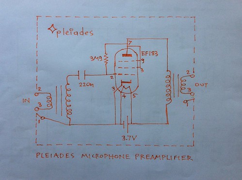
Other V series low noise microphone booster amplifiers operating with conventional electron tubes: The Pleiades V2, V3, V4, V5 or V6 with electron tubes such as 12AU7 with 6V to 4V. The EF183 variμ pentode triode connected or the Nuvistor 7586 operated with 3.9V for heaters and the anode from 3.9V to 500mV. The 2DS4 operating with an AA 1.2V battery for both heater and anode supply. Pull up or Pleiades bias resistor is normally connected from anode to grid as it was found by microphone amplification listening tests to produce an even more natural sound. The reason is not known, possibly negative feedback?.


If you know more about the history please post references.


Aknowledgments to Jeff Duntemann for his article on tubes running on 12V on the plates. To Hliana Stalika for pointing out the importance of pull up biasing for liberating the electrons. To Stephen Keller and to Merlin Blencowe for many important references and information on Merlin Blencowe's article Triodes at low voltage. To Emilio Ciardiello and parts-ring.com for the Philip B. Clark no plate supply reference. To Sean Davies for pointing out his successful use of electrometer electron tubes for condenser microphone head amplifiers.


References:


Tubes vs Transistors (vs op amps), is there an audible difference? - Russel O. Hamm - JAES


Operating features of the Audion - E. H. Armstrong


A study of Noise in Vacuum tube and attached circuits - F. B. Llewellyn - PRoc.IRE vol8 no2 Feb 1930


Fluctuation Noise in Vacuum Tubes - G. L. Pearson - Bell Telephone Laboratories - Physics Vol 5 Sept 1934


Neumann U47 report - BBC research department
http://downloads.bbc.co.uk/rd/pubs/reports/1954-23.pdf


Vacuum-tube circuits without plate supplies - Philip B. Clark - Electronics December 1952
https://www.americanradiohistory.com/Archive-Electronics/50s/Electronics-1952-12.pdf


Low Plate-potential tubes - Radio and Television News - January 1957
http://www.rfcafe.com/references/radio-news/low-plate-potential-tubes-january-1957-radio-television-news.htm


https://en.m.wikipedia.org/wiki/Nuvistor


Tube overdrive pedal operable using low voltage DC battery eliminator - Brent K. Batler - US5022305 Patent
https://worldwide.espacenet.com/searchResults?submitted=true&locale=en_EP&DB=EPODOC&ST=advanced&TI=&AB=&PN=US5022305&AP=&PR=&PD=&PA=&IN=&CPC=&IC=&Submit=Search


The Pleiades V1 operating with just an AAA battery - euroelectron


Pleiades Electra schematics - euroelectron
http://euroelectron.blogspot.com/2014/07/pleiades-electra-schematics.html


Pleiades V6 schematic - euroelectron
http://euroelectron.blogspot.com/2017/07/pleiades-v6-schematic.html


Pleiades V6 schematic


http://www.junkbox.com/electronics/lowvoltagetubes.shtml


The Pleiades Bias - euroelectron


Are there electrons or protons that do not have electric charge?


Contact potential and grid current of vacuum electron tubes


Especially at low plate voltage...


Contact potential between electrodes should be nothing else than the inducted charge on the electrodes by the boiling electrons form the heated cathode. This is possibly not to be confused with contact potential when dissimilar metals are between conductive paths.


Grid current especially at low plate potential should be nothing more that cathode electron emission current. Elscteins which have a negative charge find a path through grid or anode etc to return to their beloved protons which have positive charge. When such a path is made possible by an external resistance etc, grid or anode current etc flows. By electrostatic attraction.


This must be love.


See previous posts.


Pleiades concepts and schematics are nothing else than other electronic engineer's ideas combined together


For example the Pleiades V6 booster schematic


Hello to Australia


Hello to Russia and Switzerland


The history of low plate voltage post must be updated


Is Philip B. Clark the inventor of pull up grid bias for low or no plate voltage operation?


Vacuum tube circuits without plate supplies - Philp B. Clark


Page 192 -
https://www.americanradiohistory.com/Archive-Electronics/50s/Electronics-1952-12.pdf


The only catch is this.


Although the brilliant author seems to understand what is happening, the bias batteries are shown in pull down orientation rather than pull up.


Is this an editorial miscorrection? Must it have been difficult for an editor to accept a schematic showing positive supply toward the grid rather than negative when nearly all the schematics on the planet show the negative towards to grid?


Having said that when fixed bias is shown on a different figure by an external rectifier supply circuit the +4V is clearly shown as pull up bias through a resistor towards the negative self biased grid.


The best way to find the truth is possibly building the brilliant author's circuits that operate with no other external plate supply than the anode circuit connected to the positive cathode because of its missing electrons.


Another way to look at it is the following.


When a heater voltage is connected to an electron tube... The grid becomes negative with respect to cathode and also the anode becomes negative with respect to cathode but less so.


Any careful experiment with electron tubes (a series fuse should be used with heater supply for safety) shows typically -700mV to grid and -50mV for example to anode as soon as cathode temperature increases.


How do no plate, (anode) supply powered electron tubes operate?


When a heater voltage is applied to an electron tube boiling electrons create a negative potential on the grid (typically -700mV) and a negative potential on the anode (typically -50 or more mV?), all with respect to the cathode (which has become positive by the missing electrons).


So if we connect an output transformer from plate to cathode or a load resistor from plate to cathode in fact we are supplying a small positive potential to the anode.


Electrons start to flow.


See also nearby posts.


A ready to distort electron tube amplifier?


A musical instrument or a microphone input transformer driving an electron tube stage with no plate or anode voltage supply. See previous posts.


Distortion here means electron tube processing at the peaks or large signals.


Small signals can still be in the linear part of the transfer characteristic.


Microphone signals for example can be small. And the earth itself is flat for small travels around a stationary or operating point.


The no plate supply stage can then drive another such elcteontube stage or a JFET and then even a bipolar transistor can be driven.


The concept here is getting the electron tube processing as early or closest to source as possible.


Friday, July 20, 2018

Hello to France


Electron tubes operating with no anode supply


Vacuum-tube circuits without plate supplies - Philip B. Clark
Article begins on page 192
https://www.americanradiohistory.com/Archive-Electronics/50s/Electronics-1952-12.pdf


More articles on low, no plate voltage


https://www.radiomuseum.org/forum/tubes_operating_without_anode_supply.html


Vacuum-tube circuits without plate supplies - Philip B. Clark
The article begins at page 192:
https://www.americanradiohistory.com/Archive-Electronics/50s/Electronics-1952-12.pdf


In fact the Pleiades V1 much be one of them as it was discovered by chance while short circuiting from load resistor to filament heater (+1.5), with the Vb battery removed, the electrometer electron tube worked to amazement and this is how the Pleiades V1 microphone headamp came to life. And showing the way for Pleiades bias too.


The link was found from:


https://parts-ring.com/starved-anode-electron-tube-practices/


By searching on google for:
Starved operation of electron tubes


Is Brent Batler the inventor of pull up bias for low voltage tube operation?


On the previous euroelectron post:


http://euroelectron.blogspot.com/2018/07/explanation-of-pull-up-bias-for-low.html


Explanation of pull up bias for low voltage tube operation


On this blog it is usually called Pleiades bias.


The brilliant patent US5022305 calls it pull up bias.


The inventor Brent K. Batler received this patent on Jan 11 1991. A patent clearly ahead of its time describing the circuit of an electric guitar pedal containing an 12AX7A electron tube operated with 9V for heaters and anode circuits.


(Note the electron tube is undefeated. On Pleiades experiments eg Pleiades V6 it was found to reduce noise as we may also know from the Neumann U47 schamtic)


Brent Batoer goes on to show by comparison that for low supply voltage the use of a pull up resitor from Vb=9V to grid increases headroom, reduces distortion, gives a higher range of overload characteristics, increases input impedance, compared to a grid to cathode resistor biasing. And most of all this is for just 9V Vb or anode supply. (Would it be possible to use a pull up bias with a higher Megohm resistor (eg 60MΩ) from a higher anode voltage?)


The brilliant inventor claims he does not quite understand why this works although it is clear he is on the ball and into something great.


Various attempts have been made in previous posts to explain why pull up bias or Pleiades bias works. The term Pleiades is used in the euroelectron post but it is the same. Usually Pleiades pull up bias is applied from anode to grid as it was found to give slightly better sound quality listening to an amplified microphone in real time.


Now attempting to explain again what happens:


When the heater voltage is applied to an electron tube, the cathode temperature increases, the thermal motion of free electrons increases. Some of them can then escape from the cathode. They leave (positive) protons behind. So the cathode becomes positive with respect to grid. Ie the grid becomes negative wrt cathode. This is by definition negative bias. The electron tube is clearly cutoff at a low anode voltage. In fact it is may well be the protons not allowing further freedom for electron or so,thing happening to grid accumulating some electrons? [Armstrong]. This negative bias can be measured by a voltmeter between cathode and control grid. (A fuse in series with the heater suplly voltage should always be included for safety).


So the cathode heated electron tube looks to the external world like a source of negative voltage between grid and cathode of a certain output impedance which could be of the order of (10-100)KΩ? See previous posts.


The grid bias (space potential) is typically -700mV and becomes even more negative with increasing the heater voltage and less negative with decreasing the heater voltage ie the cathode temperature. -700mV is a typical value measured in an EF183 underheated to Vheater=4V.


If a grid to cathode bias resistor is connected it is still a pull up resistor since the cathode is 700mV more positive. This explains why decreasing Rgc increases the anode current. The grid bias is forced to become less negative. This also explains why there is grid current flowing in this resitor. In fact we have connected a load to a battery or a source of EMF. The electron tubes starts operating by not very well at low anode or plate voltage or potemtial.


When we connect a higher resitor form Vb or anode to grid it is again pull up bias by a higher potential and the pull up resistor can be higher therefore increasing the input impedance of the stage.


For example using a 6MΩ pull up resistor from anode to grid when the anode is supplied by 4V (EF183 triode connected), the grid potential becomes -70mV from the previous mentioned value of -700mV. The electron tube sings with headroom, sensitivity or low noise. See the Pleiades V6 microphone booster schematic:


Pleiades V6 schematic


On his patent Brent K. Butler shows a brilliant electric guitar amplifier schematic clearly so much ahead of its time.


https://worldwide.espacenet.com/searchResults?submitted=true&locale=en_EP&DB=EPODOC&ST=advanced&TI=&AB=&PN=US5022305&AP=&PR=&PD=&PA=&IN=&CPC=&IC=&Submit=Search


He goes on to show a comparison between an 1/2 12AX7A stage biased with 6.8KΩ from cathode to grid and the same electron tube triode biased by 100KΩ from 8.5V positive suplly to grid. The anode load resistor in both cases is 22KΩ.


The input Z is only 6.8KΩ in the first circuit and 100KΩ in the second. Output Z is the same.


The output voltage in the first circuit is only 0.7V RMS with severe clipping.


The output voltage on the second circuit is 1.2V RMS and the waveform still looks like a sinewave.


This is possibly explained by the fact that higher pull up bias or Pleiades bias takes the grid away from heavy negative cutoff so the amplifier operates in class A with electrons flowing all the times currying the glory of the music signal from control grid to the anode supplied by a small positive accelerating potemtial.


There should be more to be explained as it is assumed that the small cathode to grid resitor also biases or pulls up to a class A operating point. Further investigation may be needed.


If Brent K. Butler is the first who have thought the pull up bias, Well Done!. So far the earliest publication that was read is his patent US5022305.


Further reading:


Patent US5022305
https://worldwide.espacenet.com/searchResults?submitted=true&locale=en_EP&DB=EPODOC&ST=advanced&TI=&AB=&PN=US5022305&AP=&PR=&PD=&PA=&IN=&CPC=&IC=&Submit=Search


The Pleiades bias - euroelectron


On preserving transconuctance of electron tubes at an anode potential as low as 3V - euroelectron


Operating features of the Audion - E. H. Armstrong


Triodes at low voltages - Merlin Blencowe


http://www.paia.com/ProdArticles/tubesnd.htm


Techniques for application of electron tubes in military equipment - Rex Whitlock - page 1-10 to 1-14


Thursday, July 19, 2018

Music lessons teaching a polular song for each key


For example piano lessons using the notation on Bach Bass rules (figured bass).


For the C major scale or key Imagine - John Lennon may be a good example.


The code for each 4 bar measure:


C imagine there's no
F heaven
C9 resolved to C it's easif you
F try
C9 resolved to C
...
F imagine
E246 all the
D7 people
D246 ...
G ...
G7 ...


Or it could be Let it Be - Beatles, again which is also C major key. Or Whiter Shade of Pale - Procol Harum (based on Bach air on G string).


Next song could be one in A minor, the relative of C major. Both have only white keys.


Next song could be one in G major and then one in its relative E minor. They both have all white keys except F which is F sharp. So they define the same 7 chords.


Then D major and B minor etc.


Reference:


Bach bass rules:
https://normanschmidt.net/scores/bachjs-general_bass_rules.pdf


A patent showing low voltage operation of vacuum tubes, valves


It is US5022305


https://worldwide.espacenet.com/publicationDetails/biblio?II=0&ND=3&adjacent=true&locale=en_EP&FT=D&date=19910611&CC=US&NR=5022305A&KC=A


By Butler Brent K


Some more information on Brent Butler' history:


https://www.butleraudio.com/about.php


See also the commercial history of the guitar distortion pedal:


http://www.kitrae.net/music/Music_mp3_Tube_Driver_Versions.html


Hello to France and Vietnam


Top pageviews by Portugal, France this week


Hello to Germany


Hellas is gradually out of the civilization crisis, Η Ελλάδα σταδιακά φεύγει απο την πολιτισμική κρίση


At your own risk. This is not a medical advice.


This lost may have errors. Please do your own research.


The good news is that more and more of the young population discovers the difference between the excellent dinkel or spelt, emmer wheat made to bread and common white flour made to sticky bread. They eat it more and more in bread and other food. For some strange reason they do not fancy as much white bread possibly because they may be feeling the internal glueish gluten in their body, brain etc.


For similar reasons they avoid white sugar.


They also begin to be very interested in food such as whole sesame and tahini which has a reputation of being beneficial to the body and not clogging blood arteries like the common cheap vegetable fat used in cheap snacks, ice cream, crackers, biscuits, doughnuts, croissants made with cheap vegetable oil like palm oil etc.


So their brain and body begins to function greatly and constructively like other European citizens who had discovered the importance of dinkel for the well being of their citizens and society in general.


In hellenic mythology spelt (Ζεια) was a gift to the Hellenes by the goddess Demetra  [wikipedia].


Reference:


https://en.m.wikipedia.org/wiki/Spelt

Wednesday, July 18, 2018

A great example of the G Dorian scale...


Is the vocal solo part of the Great Gig in the Sky - Pink Floyd.


The ancient and so modern sounding G Dorian is like the G minor scale but the E in not flat but natural.


So all notes are white or natural except only B which is B flat.


So when the bass is C the 1.3.5 rule gives C E G and since E is natural the chord is major or happy.


The code at the solo part in Bach figured bass notation is:


G7
C9
G7
C9
G7
C9
....
Etc


So G7 means, G bass, then on the right hand the 7th natural note which is F. Then adding the 3rd which is B but remember B is B flat, and the 5th which is D.

So C9 means C bass, the 9th counting all natural notes which is D, and then adding the 3rd which is E, also adding the 5th which is G, also the 7th which is B but remember B is B flat.


So it is played:


G bass with G Bb D F
C bass with G Bb D E


Note the brilliant laziness rule in making the least change for a given result and how nice it sounds.


It is great playing this together with Pink Floyd.


Further reading:


Bach bass rules:
https://normanschmidt.net/scores/bachjs-general_bass_rules.pdf


The dark side of the moon piano, vocal score


Welcome to Bosnia & Herzegovina and Lebanon


Hello to Germany


An easy way to make a tube pre-amplifier, mic booster, instrument etc


Your own risk. Even a battery voltage can be dangerous. A fuse should always be used in series with a battery for safety. And all other precautions should be strictky followed.


It is a battery powered electron tube front end amplifier and the size can be the size of a small guitar pedal. The battery can be inside too.


It is based on Pleiadss V6 or Pleiades V4.


Pleiades V6 schematic


With the following simplifications...


If a low voltage heater electron tube is used then the battery can be just one AA 1.2V supping both heaters and anode. The Pleiades bias grid resistor from anode to grid can be 1.8MΩ.


Suitable electron tubes can be the electrometer CV2269 or Nuvistor 2DS4, 2CW4, 2DV4. Also 4BC8 which may be underheated with a good effect with 1.2V but possibky this would be too extreme. So 2xAA batteries. In this case the anode voltage can be 2.6V which should be plenty. If not then 6.3V heater electron tubes can be used with 3 AA or AAA batteries, such as EF183, Nuvistor 7586 etc. Underheating can produce a very impressive signal,to noise ratio. See previous posts and the Neumann U47 schematic with the VF14 electron tube deliberately underheated by Georg Neumann.


Now why spending time drilling holes and mounting input or output transformers where they can be external?


Impedance converters with a transformer inside an XLR to 1/4in jack adapter can be used and are easy to find. And one can play with various types and primary inductance for the right hiss pass needed for a specific application. See all 3 generation Pleiades filters and transformers.


So all needed:


A top quality battery holder such as Bulgin. The amplifier is sensitive and revealing so the contacts must be top quality to avoid noise.


2 female 1/4in chassis sockets, eg Neutrik.


A fuse holder.


A switch for the heater voltage.


A Pleiades bias resitor from anode to grid.


A coupling capacitor to grid.


That should be it.


It may be possible to directly connect the amplifier to an electret mic in device. At your own risk, see previous post.


It has hi Z in hi Z out. A load resitor might be needed if the next device or stage does not have one. At your own risk.


All other low Z balanced in or out combinations can be done by plugging in suitable XLR impedance converter adaptors with a signal transformer inside them.


Anode might be connected all the time and the heater circuit connected by a 1/4in female chassis socket with switch when a 1/4in jack is plugged in.


Rag may be variable for best sound. A heater series resistor may also turn out to be very interesting sound wise or noise wise.


See also:
http://euroelectron.blogspot.com/2018/07/connecting-electron-tube-instead-of.html


Further reading: The Pleiades Bias - euroelectron