On this blog it is usually called Pleiades bias.
The brilliant patent US5022305 calls it pull up bias.
The inventor Brent K. Batler received this patent on Jan 11 1991. A patent clearly ahead of its time describing the circuit of an electric guitar pedal containing an 12AX7A electron tube operated with 9V for heaters and anode circuits.
(Note the electron tube is undefeated. On Pleiades experiments eg Pleiades V6 it was found to reduce noise as we may also know from the Neumann U47 schamtic)
Brent Batoer goes on to show by comparison that for low supply voltage the use of a pull up resitor from Vb=9V to grid increases headroom, reduces distortion, gives a higher range of overload characteristics, increases input impedance, compared to a grid to cathode resistor biasing. And most of all this is for just 9V Vb or anode supply. (Would it be possible to use a pull up bias with a higher Megohm resistor (eg 60MΩ) from a higher anode voltage?)
The brilliant inventor claims he does not quite understand why this works although it is clear he is on the ball and into something great.
Various attempts have been made in previous posts to explain why pull up bias or Pleiades bias works. The term Pleiades is used in the euroelectron post but it is the same. Usually Pleiades pull up bias is applied from anode to grid as it was found to give slightly better sound quality listening to an amplified microphone in real time.
Now attempting to explain again what happens:
When the heater voltage is applied to an electron tube, the cathode temperature increases, the thermal motion of free electrons increases. Some of them can then escape from the cathode. They leave (positive) protons behind. So the cathode becomes positive with respect to grid. Ie the grid becomes negative wrt cathode. This is by definition negative bias. The electron tube is clearly cutoff at a low anode voltage. In fact it is may well be the protons not allowing further freedom for electron or so,thing happening to grid accumulating some electrons? [Armstrong]. This negative bias can be measured by a voltmeter between cathode and control grid. (A fuse in series with the heater suplly voltage should always be included for safety).
So the cathode heated electron tube looks to the external world like a source of negative voltage between grid and cathode of a certain output impedance which could be of the order of (10-100)KΩ? See previous posts.
The grid bias (space potential) is typically -700mV and becomes even more negative with increasing the heater voltage and less negative with decreasing the heater voltage ie the cathode temperature. -700mV is a typical value measured in an EF183 underheated to Vheater=4V.
If a grid to cathode bias resistor is connected it is still a pull up resistor since the cathode is 700mV more positive. This explains why decreasing Rgc increases the anode current. The grid bias is forced to become less negative. This also explains why there is grid current flowing in this resitor. In fact we have connected a load to a battery or a source of EMF. The electron tubes starts operating by not very well at low anode or plate voltage or potemtial.
When we connect a higher resitor form Vb or anode to grid it is again pull up bias by a higher potential and the pull up resistor can be higher therefore increasing the input impedance of the stage.
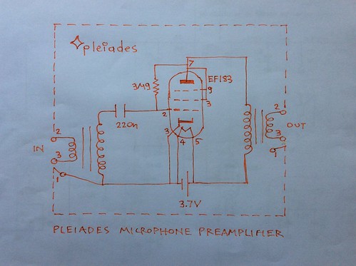
For example using a 6MΩ pull up resistor from anode to grid when the anode is supplied by 4V (EF183 triode connected), the grid potential becomes -70mV from the previous mentioned value of -700mV. The electron tube sings with headroom, sensitivity or low noise. See the Pleiades V6 microphone booster schematic:
On his patent Brent K. Butler shows a brilliant electric guitar amplifier schematic clearly so much ahead of its time.
https://worldwide.espacenet.com/searchResults?submitted=true&locale=en_EP&DB=EPODOC&ST=advanced&TI=&AB=&PN=US5022305&AP=&PR=&PD=&PA=&IN=&CPC=&IC=&Submit=Search
He goes on to show a comparison between an 1/2 12AX7A stage biased with 6.8KΩ from cathode to grid and the same electron tube triode biased by 100KΩ from 8.5V positive suplly to grid. The anode load resistor in both cases is 22KΩ.
The input Z is only 6.8KΩ in the first circuit and 100KΩ in the second. Output Z is the same.
The output voltage in the first circuit is only 0.7V RMS with severe clipping.
The output voltage on the second circuit is 1.2V RMS and the waveform still looks like a sinewave.
This is possibly explained by the fact that higher pull up bias or Pleiades bias takes the grid away from heavy negative cutoff so the amplifier operates in class A with electrons flowing all the times currying the glory of the music signal from control grid to the anode supplied by a small positive accelerating potemtial.
There should be more to be explained as it is assumed that the small cathode to grid resitor also biases or pulls up to a class A operating point. Further investigation may be needed.
If Brent K. Butler is the first who have thought the pull up bias, Well Done!. So far the earliest publication that was read is his patent US5022305.
Further reading:
Patent US5022305
https://worldwide.espacenet.com/searchResults?submitted=true&locale=en_EP&DB=EPODOC&ST=advanced&TI=&AB=&PN=US5022305&AP=&PR=&PD=&PA=&IN=&CPC=&IC=&Submit=Search
The Pleiades bias - euroelectron
On preserving transconuctance of electron tubes at an anode potential as low as 3V - euroelectron
Operating features of the Audion - E. H. Armstrong
Triodes at low voltages - Merlin Blencowe
http://www.paia.com/ProdArticles/tubesnd.htm
Techniques for application of electron tubes in military equipment - Rex Whitlock - page 1-10 to 1-14
No comments:
Post a Comment