Attention: always use a suitable fuse in series with a voltage for safety. Take all necessary safety measures even when working with small voltages as on this experiment.
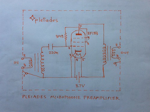
Will it make a nice microphone booster or head amplifier with just 1.5V for filament and plate (anode) using the Pleiades V6 schematic?
This is on only using very small voltages, typically below 9V.
On this experiment with the 1H4 electron triode tube only 1.3V is used.
The electron tube is pluged in and supported by a Finder 90.20 octal base relay holder.
First the heater was supplied trough 10Ω in order to gently heat it and avoid a heater current spike or surge by the low resistance of a cold filament wire. A hotter wire has more resistance to electric current as its molecules vibrate more and there is a higher chance for electron collision while electrons flow (current flows).
Next 1.2V was connected to the heater or filament or cathode.
The heater current at approx Vf=1.3V is 40mA.
The control grid becomes more than -200mV with respect to the (-) terminal of heater. Since the direct heater filament is supplied by 1300mV and half of it is 650mV, this means the grid is about -850mV with respect to the central value of cathode.
A microammeter was connected between any terminal of the filament cathode and anode and there was no anode current that could be measured. It must be very small?
Obviously we would need pull up bias or Pleiades bias for any chance to make the electron tube operate at a so negative grid and 1.3V anode potemtial.
A micro ammeter was connected across rather than through. Blown fuse. 400mA fuse replaced. Time delay.
No measurable current at 1.2 volt plate voltage. There may be sound out, not checked yet. Later addition. It was measured 0.1μA using a pull up resistor from 9V to grid of 8.2MΩ. 0.1μA the pull up resistor connected to 1.3V.
At 9V plate supply, with free grid, Ia is 20μA. The potemtial difference between negative filament and grid becomes 50mV. So the free grid bias should be -600mV under the influence of the filed of the anode, or change of the distribution of space charge electrons inside the electron tube from cathode to anode?
With a Pleiades bias pull up resistor or 8.2MΩ, Ia is a mighty 140μA, 100mA from an older used tube. 77μA with the 8.2MΩ pull up resitor connected to 1.3V. See also other today's post on letting the electron tube decide its operating point without pull up or pull down bias on the control grid. It cannot be decided yet which is best. see also Pleiades V(-1) with UCC85 free grid.
2μA with a 2.7MΩ pull up resitor from 1.3V to grid and plate supply of 1.3V. Same pull up but plate supply 9V, Ia=93μA.
Now adding another AA battery just for the plate, in total 2 batteries. So heater supply is 1.3V, plate supply is 2.6V. With pull up resistor connected to 1.3V, Ia is 1.3μA. With pull up resitor connected to 3.6V, Ia is 3.8μA. It should be possible to have a booster microphone amplifier. From rough measurements grid bias still looks negative. A lower resitor than 2.7MΩ could be used but best to do is listen and see what happens. (Attention to ear protection, all safety measures should be followed).
Why so low current at 1.2V? Possible cause... From basic physics on electricity, electric field intensity is voltage : distance, change of potemtial over change of position ΔV/Δx. A larger tube would have the electrode elements more spaced therefore less electric (pull) field for given applied electric potential between cathode and plate.
Next day's experiment Is a test with a microphone. The free grid option sounded brilliant. 9V was used for the plate, wing or anode.
http://euroelectron.blogspot.com/2018/07/1h4-with-grid-at-space-potential-mic.html
Important addition: the grid space potential increases from -150mV to +50mV when 9V is applied to the plate:
http://euroelectron.blogspot.com/2018/08/the-grid-space-potential-increases-when.html
No comments:
Post a Comment