Attention. Any voltage can be dangerous. At your risk. Take all safety precautions. Also a suitable fuse should be used with any battery for fire hazard protection.
It is beginning to get more interesting.
Today it is the first time on Pleiades experiments that a magnetic tape recording head is connected directly to anode or plate. In place of an output transformer.
So there is treble rise due to the high output Z of electron tube (as is done with all analog tape recorders since the head (inductor) is driven at constant current). And there is DC at least bias of the magnetic tape as the anode is direct coupled to recording head in an attempt to operate it at its linear BH characteristic. And attempting to use the minimum possible number of components.
Summary: At 250μA to 500μA anode or recording head (quiescent or DC current) it worked. It was possible to record a cassette at least up to +3VU. There was more treble compared to connecting the 2N3053 transistor as recoding amp due to the higher impedance of the electron tube. But the Pleiades 2N3053 has been tried only operating from 1.3V whereas the EF183 electron tube was tried today at a range of plate potentials from 3.6V to 12V.
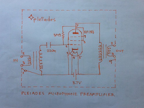
The Pleiades V6 schematic was used without input transformer and with the recording head of a Tascam Porta 03 transport instated of the output transformer. Pleiades bias or further pull up bias from anode to grid was used to shift away the electron tube from cutoff and make it operate the usual way with just few volts at the plate.
A range of anode currents i.e tape DC bias currents from 2.5mA to 200μA were tried. They were produced by only changing the Vb or plate (anode) supply of the Pleiades V6. And also by under heating the cathode by disconnecting the heater supply observing sound quality change as the cathode temperature decreased.
A time lag exists for listening tests as the cassette has to be removed and played to a Sony TC-D5 Pro II each time a change to recording conditions is made.
Referring to the Pleiades V6 schematic:
If no Rag resistor is used (no Pleiades or further pull up bias) the grid is negative to cutoff since the cathode thermally emitting its electrons becomes positive. The electron tube is sleeping.
Both electron tube and magnetic tape are at cutoff. As soon as the electron tube negative bias is decreased by Rag both electron tube and tape wake up as the tape is no longer at its low part of positive quadrant cutoff. By biasing the electron tube, the tape can be biased too at its center point of the straight part of the positive quadrant BH curve.
It sounds the electrons are waking up.
In fact electrons are always at thermal motion or noise agitation waked up by the sun. The electrons in the cloud around cathode are at greater thermal motion by the nearer cathode at high temperature. What do electrons, spinning or orbiting ones? do inside the tape magnetic domains? Who knows?
2 channels of Pleiades V6 amplifiers had already been sort of prototyped from previous experiments directly driving the Sennheiser HD580 300Ω per channel headphones. At the moment one channel was only connected to recording head, L channel part of side A.
Referring to Pleiades V6 scheMagic, instead of an input transformer there is a potentiometer. A CD player line out is feeding it.
Signal path on recording:
Is it OK? 06 track of Fame soundtrack on CD - Sony portable CD player line out - Pleiades V6 with Cc=22nF, Rag=1.5MΩ - recording head of Tascam Porta 03 instead of output transformer - TDX SAX 60 type II cassette running at normal speed
Signal path on playback:
TDK SAX cassette - Sony TC-D5 Pro II - Sennheiser HD580
These Pleiades V6 amps used were kind of optimized for direct driving the HD-580 headphones, see Pleiades Electra 3.
This was done by reducing the EF183 internal plate resistance by increasing as much anode current at low plate voltage. This was done by a relatively low ie 1.5MΩ pull up bias resistor from plate to grid. Circuit fed by 12V. The output impedance should be around 5 KΩ which may be too low for driving a tape recording head. So such heavy pull up bias may be a disadvantage.
So here is how the first Pleiades recodings with anode direct to tape were done. All batteries must be used in series with a fuse for safety including fire hazard. Various Vb, anode supply voltages needed were created by various series combinations of AA rechargeable batteries.
A 12 V battery is powering 2 EF183 electron tubes (for each channel) heaters in series. So there is no deliberate imderheating. This too proved to be possibly a disadvantage.
But let's see how the head was driven by various plate supply potentials.
Initially HD580 headphones were connected at anodes to check everything sounds ok. The sound was amazing. With fantastic treble for a CD reproduction.
Then the head was connected. Surprise. At reproduction there was no sound. Only some deep heavy hiss. It was apparent that the tape was saturated by anode current. Ia was measured 2.7mA so tape bias was 2.7mA DC.
Then plate supply or Vb was changed to 3.6V. Unfortunately the potentiometer was by mistake reduced to a lower signal input to the EF183. It worked. There was sound. Modulation was a few dB below 0VU. Ia was 250μA.
Then Vb was changed to 7.2V and another recording proceeded. Ia=1mA. Almost no sound. There was sound only when disconnecting the heaters while cathode temperature was being reduced.
But then accidentally while reconnecting the HD580 to check something and after increasing signsl input to EF183, they were left connected by mistake. The recoded sound was great. Tape modulation as seen on playback was +3VU, there was no distortion. Treble of course was lacking as the output impedance was lowered by the headphones. It seems the headphones shared the current and indeed the DC bias was 600μA. So this may be a value to aim for.
Then headphones disconnected and Vb=6.5V was used giving a DC bias of 700μA. At last it started working. There was treble loss. And modulation increased for same conditions when disconnecting heaters. It seems 700μA is too much.
Then Vb=5.5V was used. Anode current or DC tape bias was now 500μA. Great. Modulation increased. It worked. There was treble loss. Hiss was kind of thick midband. Barely head when music was playing.
Then Vb=3.6V was used again but this time driving the EF183 more at the input. It worked. There was more treble. More distortion. But a nice sound. Hiss seemed to be less. Disconnecting heaters with no music playing gives a chance to hear how bias noise reduces to the so low value of the virgin tape as cathode reduces emmision of electrons.
Conclusion:
Bias values from perhaps 200μA or less to 500μA might be aimed for.
For increasing treble, the impedance of the amp has to be increased. Ie increasing output voltage but reducing output current and certainly the quiescent anode current. What is needed is an increase in power by increasing supply voltage but without increasing the anode current. The recording head is an inductor and can be driven at constant current with respect to frequency ie rising voltage with rising frequency. This is done by driving the head with a high output impedance.
So for example Vb=12V can be tried but with much less pull up bias. For example arranging Rag so that Ia is 400μΑ.
Or even Vb=18V with no pull up bias?
How would the circuit sound by leaving the grid at space potential and supplying anodes by 18V?
See also part 3:
https://euroelectron.blogspot.com/2018/10/connecting-electron-tube-anode-to.html
No comments:
Post a Comment