Not to be confused with an ordinary low cut filter of a mixing desk or preamp which may usually be 12dB per octave or more.
Here as well as the previous euroelectron posts 6dB per octave or less are of concern. Cutoff (turnover frequency) may even be placed at a frequency of more than 700Hz. These filters are intended to compensate for various bass boost effects, objective or subjective (to our ear-brain) so that the end result is flat frequency response from singer's brain to listener's brain. Or from record producer's brain to listener's brain. See previous posts.
These effects have been mentioned on previous euroelectron posts. 3 very important ones are: the proximity effect (objective), Fletcher-Munson or equal loudness curves (subjective or brain perception) and the voice effort effect (objective) [Lowe, Morgan].
Where is it best to low cut? Before the mic?, just after the mic?, after the input transformer secondary?, at the output transformer primary?
God only knows.
Here is some food for thought.
Before the mic or at the mic may mean which mic to use and how. An omnidirectional mic will not have a proximity effect. The other 2 bass heaviness effects will be present too. A directional mic will also have proximity effect. So it would sound even more bass heavy but by increasing the singer mic distance the proximity effect is reduced in a varying way.
Now let's look at some other possible places to low slope low cut.
Refering to the Pleiades V6 mic front end:
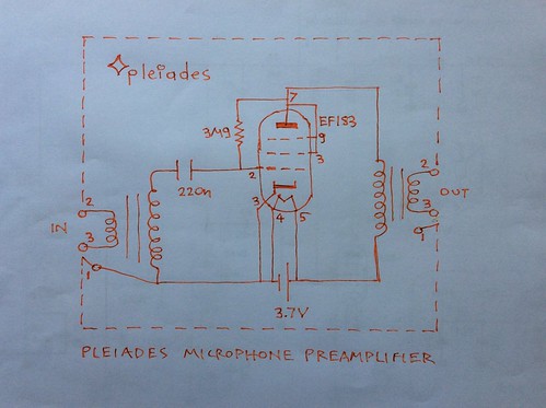
(Caution: Always use a suitable fuse in series with any battery for safety).
Beginning from the end...
It was found by chance that doing the low cut by the electron tube plate resistance (see equivalent circuit of an electron tube) and the primary of the output transformer gives possibly the best results so far on Pleiades experiments.
As the circuit is shown above the sound will be will be bass heavy. But if a higher Rag is used such as Ia drops from 50μA to say 10μA the sound would be great.
Specifically about 10μA current was achieved by using the EF183 with Va=9-12V but with no grid resitor ie at space potential. Same for an 1H4 electron tube.
Or using EF183, 7586, or 2DV4 at 1.3V plate potential with a 1.9MΩ from anode to grid. The 2DV4 has the advantage of being 2V for heaters. So both deliberately under heated cathode and plate at low potential can be supplied by the same 1.2V or 1.5V battery. (Always a suitable fuse in series with a battery must be used for safety.
Low anode current sounds nice as there is the impression of no bass heaviness and at the same time that no low cut is applied. It apparently works by the higher anode resistance of the electron tube forming an RL circuit with the output transformer primary inductance. The phenomenon is not fully understood. Perhaps a more gentle than 6dB per octave slope is being created by the high resistance of the thin primary winding creating in effect an (R,L) Pleiades filter.
Now let's look ar some other places.
It may be an inductor in parallel with the mic output. (See Pleiades filters). It sounds nice but not too nice. A possible cause may be the relative high 6dB per octave slope. Also the magnetic core saturating by the heavy bass from the mic. But if there is a resistance in series with L the slope decreases and the sound becomes much more listenable. See Pleiades (R,L) filters.
Other way is to use an input transformer of such material (mumetal?) that the inductance too varies with frequency. See a post on a Freed military mic input transformer. This can vote a slope of less than 6dB per octave.
Other way is to use a transformer primary made of resistance wire or of a very thin wire. Not tried yet.
Another way is a capacitor after the mic. On the V72 schematic a capacitor can be seen connecting 2 halves of the primary winding. Is this a low cut filter? In general not good sound has so far been produced by low cutting with a capacitor. More experiments are needed. Another way is to include a resistor in parallel with the capacitor in order to reduce the slope. A resitor also crates a shelling filter. See next post.
And another obvious place is the Cc capacitor. Not as good as expected results have been obtained so far by varying Cc with a capacitor box. It works but the slope is still 6dB per octave which may be high. For some reason the sound is not as good as it could be. Perhaps adding a parallel resistor? But this would upset the grid potential. The grid potential would not be upset it it is arranged that the grid is connected to the same potential as its space potential. So that there is no grid current. Perhaps a variable cathode resistor etc, the use of a electrometer or PH meter to measure the grid space potential or the use of a nano ammeter may aid.
So far possibly the best sound is letting the high electron tube plate resistance and the primary transformer inductance with the primary winding resistance do the trick. A disadvantage so far is that at such a very low anode current the noise is small but not as small as it could be.
Next best or potentially better is the use of an inductor in series with a resistor just after the mic, in parallel with its output. Only 140Ω, 40mH Pleiades filters has been auditioned so far. Perhaps it is a good idea to create a variable box of inductance and series resistance. And increasing the anode current by say pull up bias or a 12V plate supply and grid at space potential so that noise becomes world class.
Another way may be just increasing Ia and reducing the number of turns of the output transformer primary. Or perhaps even better using a magnetic core of less inductance index so that more wire is needed ie a more resistive primary will be created.
More ideas are needed here.
Reference:
(Flat frequency response from producer's brain to listener's brain), Sound Picture Recording and Reproducing Characteristics - D. P. Lowe, K. F. Morgan - JSMPE
No comments:
Post a Comment