At your risk. A fuse should always be connected in series with a voltage source for safety.
Drawing on fine sand is amusing, educating,
One may use a small wooden stick and start drawing a circle, (the electron tube bulb). Then adding an anode, grid, cathode etc. then all other electronic parts and connections.
The resolution is very high as the drawing can be say a meter x more.
So many times has the Pleiades V6 schematic been drawn:
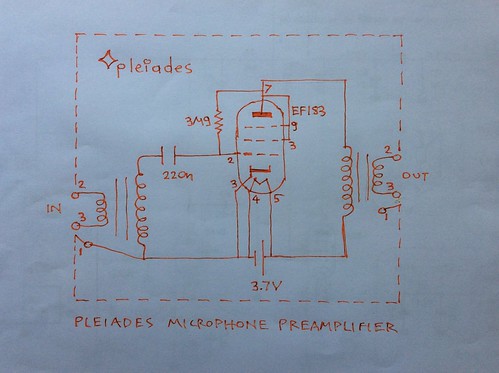
The gentle passing of sea water wave always first erases the bottom part. The battery part.
Or 2 batteries if a separate say 9V potential is sent to anode. And then the grid can be left floating, not connected to a pull up resistor, at space potential. See 1H4 for example, it's grid left at space potential.
But the water always erases this part.
Does it mean there is something to be improved?
Using for example hearing aid or electrometer electron tubes which only consume say 14mA for the filament cathode. Leaving grid at space potential? And arranging the their filament supply battery in such a way that there is an external potential equal to the space potential internaly created by nature.
So that then the input transformer secondly can be connected directly to grid (eliminating the capacitor) with no cathode to grid emission current flowing through the transformer secondary?
No comments:
Post a Comment